3 Wire Rtd Circuit Diagram. An RTD consists of a temperature-sensing element connected by two, three, or four wires that provide input to the module. These are the circuits and boards of a Mini Temperature Transmitter for a Platinum hundred ohms temperature Sensor.

Information: Catalog and Supplier Database for Engineering and Industrial Professionals.
RTD excitation is provided from the module using a precision current source.

Rtd Pt100 Resistance Table Pdf | Brokeasshome.com

3 Wire Rtd Wiring Diagram
XTR108 Three-Wire RTD Connection Circuit - Other_circuit ...
Ring Terminal Style RTD - Thermocouple-Online.com
RTD Amplifier Circuit, Measuring RTDs, Connecting RTD to ...
Rtd Pt100 3 Wire Wiring Diagram Gallery | Wiring Diagram ...
Smart Temperature Transmitter, RTD/Thermocouple/Resistance ...
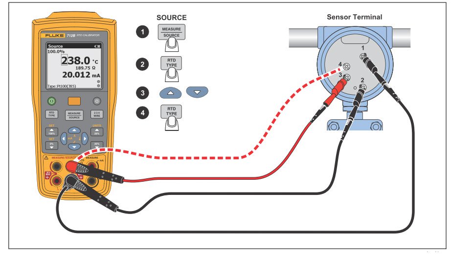
Fluke 712B RTD Temperature Calibrator | TEquipment.NET

Get 3 Wire Rtd Wiring Diagram Download
Define the range of temperature measurement using a RTD(Resistance Temperature Detector) sensor. Sensor connection RTD lead resistance may introduce errors. The voltmeters shown in the four-wire and three-wire diagrams serve only to illustrate the basic concepts, not to showcase practical instrument.
