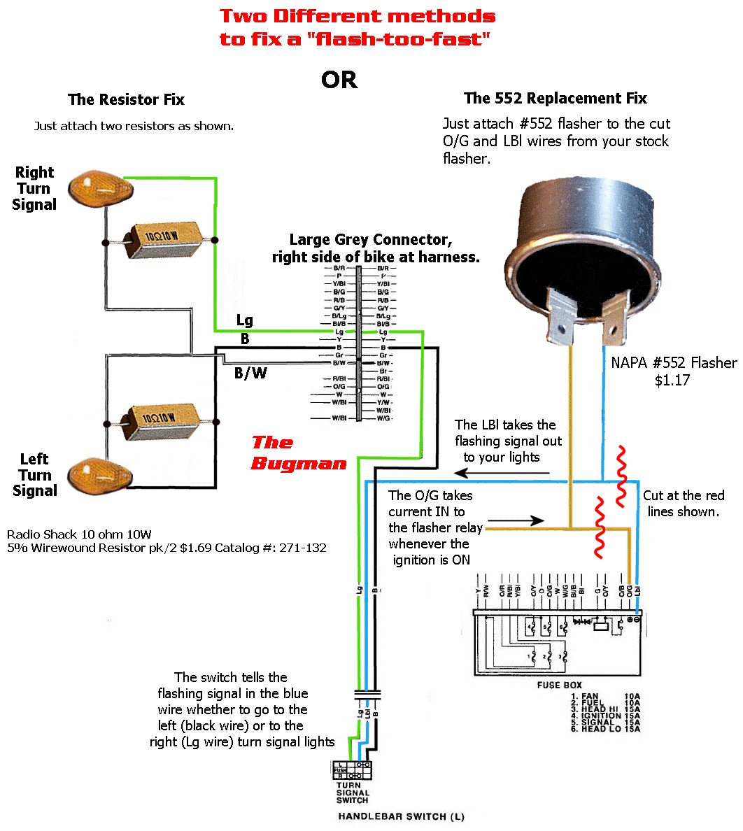
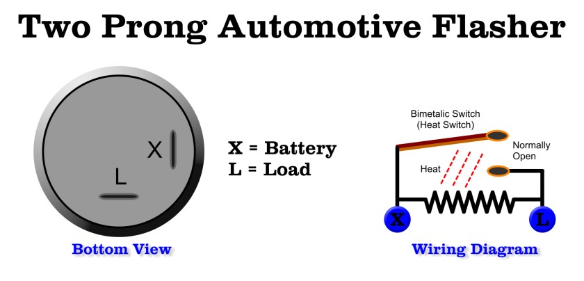
3 Pin Electronic Flasher Relay Wiring Diagram. This is a diagram for a flashing relay. Flasher relays control the operation of turn signals and hazard flashers on many cars and Flasher relays have a power source terminal, sometimes labeled "B" for battery, a load terminal labeled "L" Connect the "B" terminal to the positive terminal of the battery using the test wire with equal-length.
Note: This is for electronic relay type flashers only.
Solid State Relays switch current using non-moving electronic devices such as silicon controlled rectifiers.

3 Pin Led Flasher Relay Wiring Diagram Gallery | Wiring ...

12V Electronic Flasher/Hazard Relay 21Wx2 + 5W | 12 Volt ...
2 Pin Flasher Relay Wiring Diagram | Wiring Diagram
3 Pin Flasher Unit Wiring Diagram

2 Pin Flasher Relay Wiring Diagram — UNTPIKAPPS
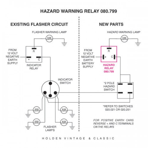
12 volt Hazard / Flasher Relay

Car Turn Signal Flasher Circuit with Lamp Malfunction ...

Tridon Flasher Wiring Diagram - Wiring Diagram

3 pin flasher relay wiring diagram manual
Flasher relays control the operation of turn signals and hazard flashers on many cars and Flasher relays have a power source terminal, sometimes labeled "B" for battery, a load terminal labeled "L" Connect the "B" terminal to the positive terminal of the battery using the test wire with equal-length. Also it can solve error message of bulb burnt out showing on instrument panel due to less power consumed by LED bulbs.. Alpha Rider Relay Turn Signal Light Flash Flasher for Led.
