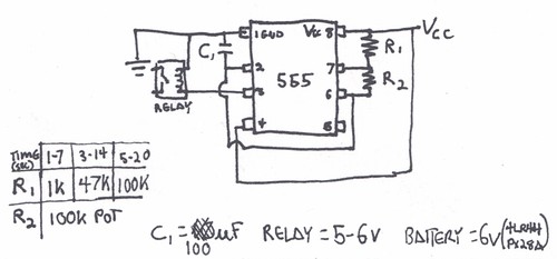
555 Timer Relay Circuit Diagram. The complete details about the circuit and its circuit diagram are given in the original article. This circuit uses a relay and a sensor to sense and switch when the light intensity crosses a certain limit.

You can watch the following video or read the written tutorial below.
Here we use the simple logic that when trigger pin is grounded, output is a high logic can this circuit works as UPS relay changeover with zero crossing detector?or it should be add zero crossing circuit?

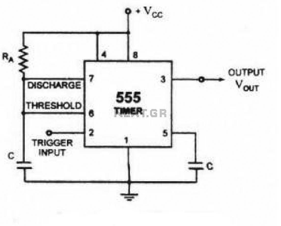
Monostable multivibrator using 555 timer | Circuit diagram ...

The 555 Monostable Circuit - More Detail

Clap Switch Circuit with Relay
Public Lab: Adjustable 555-based shutter trigger circuit
Relay Toggle Circuit Using a 555 Timer under Repository ...
Time Delay Relay using 555 Timer, Proteus Simulation and ...

Touch on Touch off switch using 555 timer IC - Elonics

Timer 555 Schematic | IC schematics
> circuits > arduino Relay takes time to close l26165 ...
The complete details about the circuit and its circuit diagram are given in the original article. A simple circuit that powers a led strip when the momentary switch is pressed, then shuts it down automatically after. Relay = As specified for the previous circuit.
