555 Timer Circuit Pin Diagram. On the last diagram we see two connections made by the component side (blue). These circuits were developed to provide certain functions that are not typically.
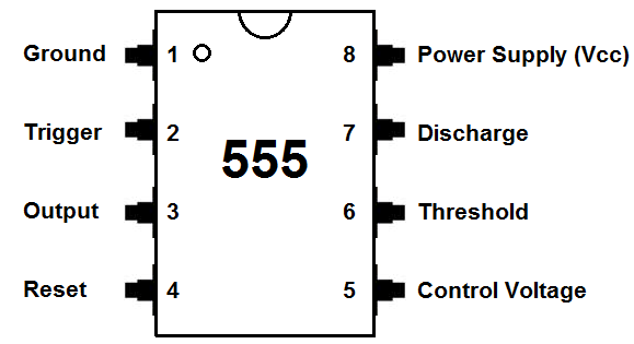
Print the diagram in the centre of a sheet of paper create a circuit using the ICs pin locations.
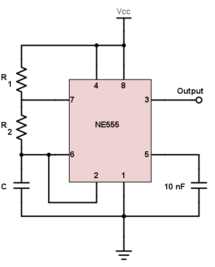
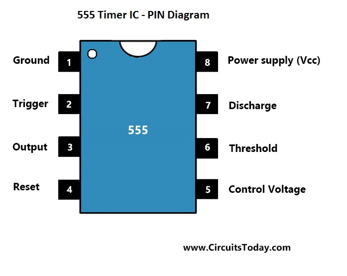
This IC is useful for generating accurate time d.

Таймер 555 - CoderLessons.com

Timer IC 555 I Timing Circuit I Block Diagram I Features
555 Timer Astable Circuit - Electrical Engineering ...

Servo Motor Controller and Tester using 555 Timer | ELECTRONIX

Familiarize Electronic Components Part XI – Timer IC 555 ...
555 Timer Astable Multivibrator Circuit – Technology & Hacking
555 Timer IC: Internal Structure, Working, Pin Diagram and ...
555 Timer IC - Electronic Circuits and Diagrams-Electronic ...

fm generation using 555 timer : Repository - Next.gr
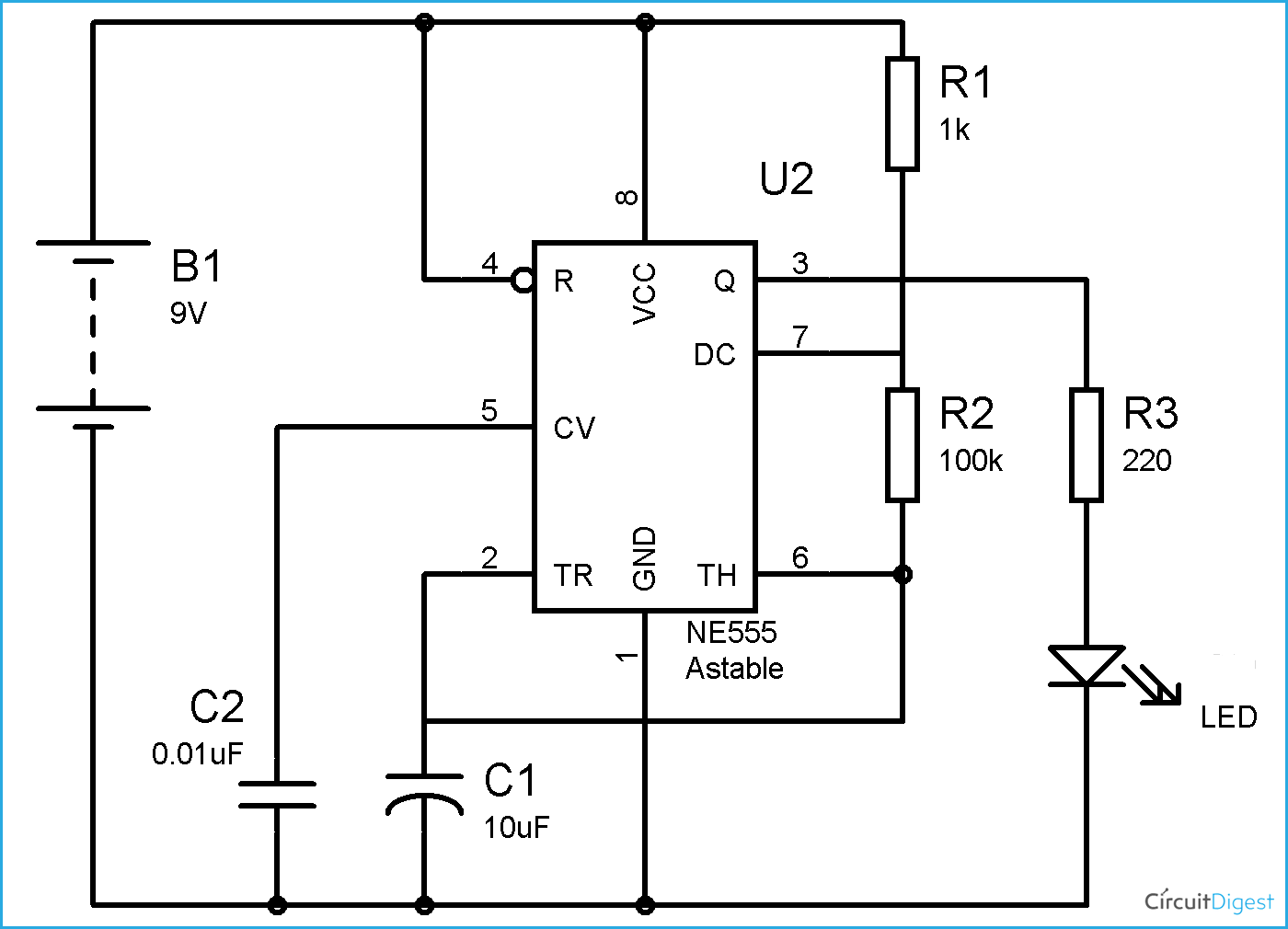
With just a few external components it can be used to build many circuits, not all of them involve timing! This waveform will turn LED ON and OFF. The next two diagrams show the proposed PCB for this circuit and an image of what would be the finished circuit.
