555 Timer Circuit Diagram. Connected Appliance with this timer circuit is automatic switch OFF after some duration of time. The simple delay timer circuit is similar and has just a few more components.
This IC is useful for generating accurate time delays and oscillations.
In our circuit, the one of the bulbs will be ON in the ON state and the other will be.
Arduino lesson – 555 Timer IC « osoyoo.com

555 timer IC - Wikipedia

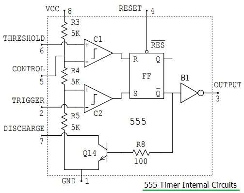
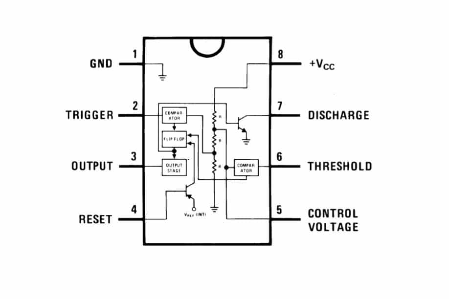
File:NE555 Internal Circuit.svg - Wikipedia
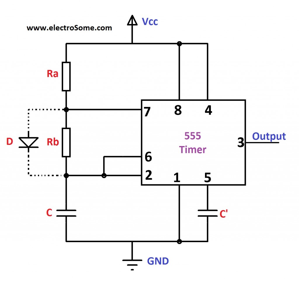
Astable Multivibrator using 555 Timer Circuit Diagram

CMOS 555 Timer: Structure Explained and Reverse Engineered ...
555 Timer Astable Multivibrator Circuit – Technology & Hacking
555 Timer Monostable Circuit Triggered When Circuit is ...
555 Timer Basics - Monostable Mode

Servo Motor Controller and Tester using 555 Timer | ELECTRONIX
Print the diagram in the centre of a sheet of paper create a circuit using the ICs pin locations. These circuits were developed to provide certain functions that are not typically. This consists of a few different elements.
