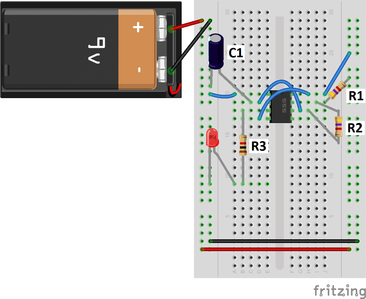
555 Timer Astable Mode Circuit Diagram. It doesn't have any stable state ie has two quasi-stable states (HIGH & LOW). The astable function can be The SPICE circuit (top figure) looks almost identical to the block diagram.
The longer lead of a polarized capacitor is the positive and the shorter lead is negative.
Its function is to discharge the timing capacitor in astable and monostable circuits.

555 Timer tutorial

Adjustable ON OFF Timer(using 555 astable mode ...
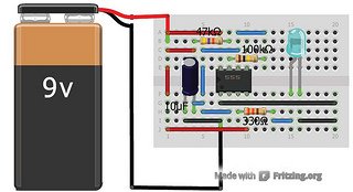
555 Timer Astable Multivibrator Circuit Diagram

ASTABLE Multivibrator Using 555 Timer | DIY | Step By Step ...
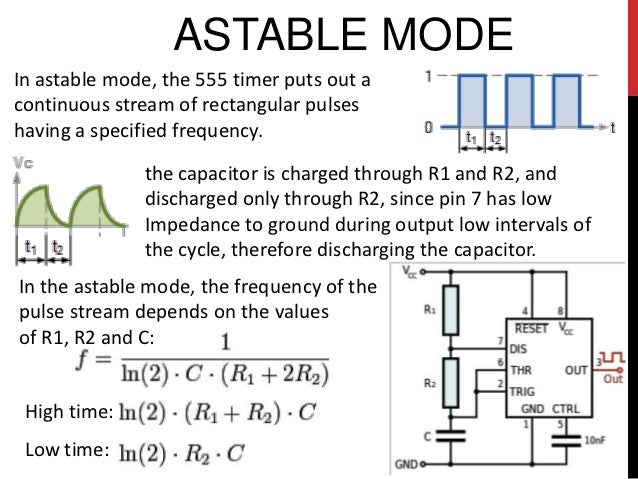
555 Timer Basics - Astable Mode
Mode of NE555- Monostable | BuildCircuit
555 Timer Operating Modes
555 Timer IC

The Astable-Oscillator Operating Mode in 555 Timer IC ...
It was a final project of electrical measurement course. IN this One in astable mode and another one in mono stable mode. Finally, power up your circuit by connecting the battery to your.
