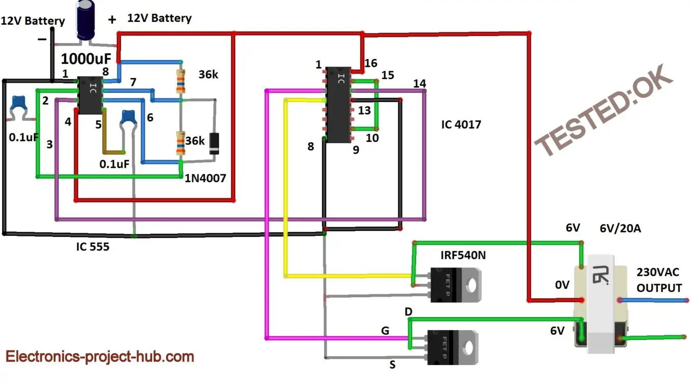
50 Hz Sine Wave Oscillator Circuit Diagram. This oscillator circuit permits crystals to be electronically switched by logic commands. Sine wave is most commonly known as waveform for Alternating Current.

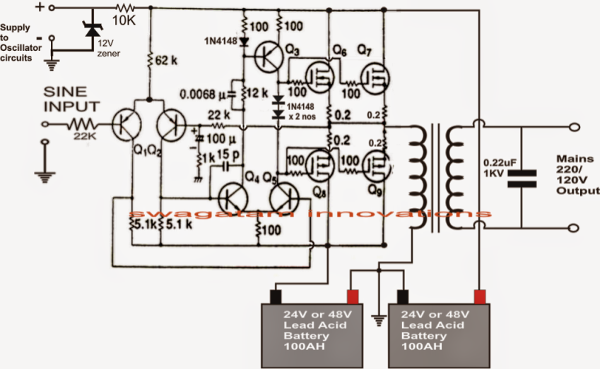
To make a sinewave inverter you need to use high current PWM modulated by the sine wave and feed it to a.
Sine wave circuits pose a significant design challenge because they represent a constantly controlled linear oscillator.
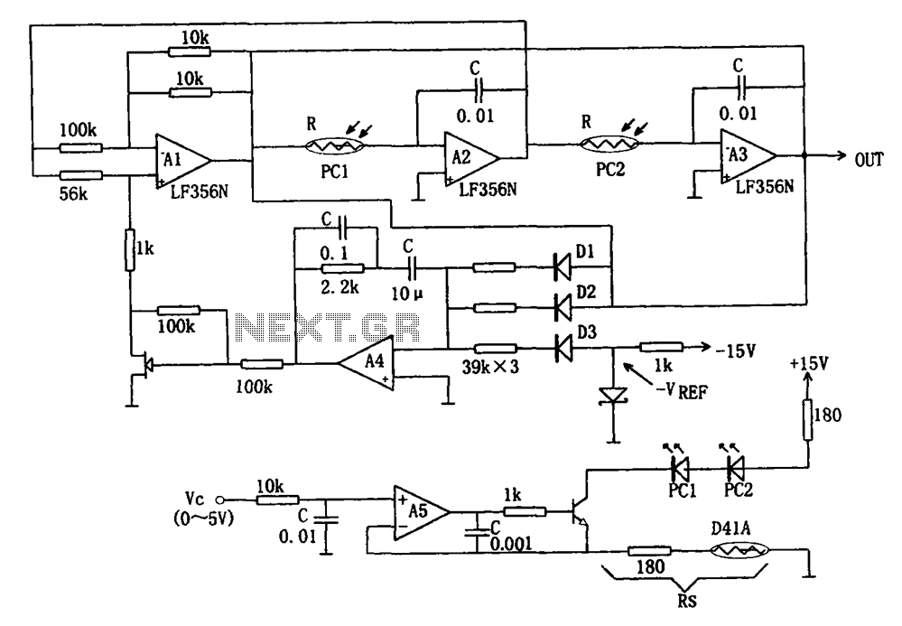
sine wave oscillator circuit : Oscillator Circuits :: Next.gr

1000 Watt Pure Sine Wave Inverter Circuit Diagram ...

Pulse Motor Generator Schematic - Wallpaperall

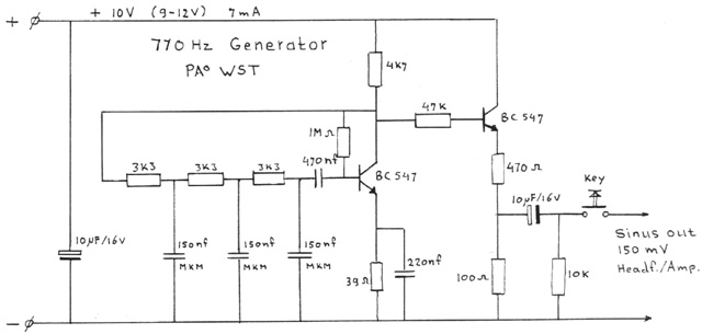
Audio Sine Wave Generator Circuit - AUDIO BARU
Digital Modified Sine Wave Inverter Circuit 250 watts ...
oscillatori
Modified Sine Wave Inverter Circuit – DIY Electronics Projects
Scematic Diagram Panel: Simple Inverter Circuit Diagram 1000w

13 Awesome 50hz sine wave generator circuit | Recycling in ...
In sine wave oscillators for use in radio transmission, the oscillator is the source of the transmitted radio wave, so frequency accuracy and stability are of vital importance as radio bands are usually crowded with many transmitters operating in a given radio band. This oscillator can be used as. I am presenting here two such sine-wave oscillators that uses RC components to generate oscillations and they can generate frequency in AF range as well.
