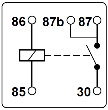
5 Pin Relay Diagram. Here we look at relay switch pin diagram and the different kinds of relay switches. When the relay receives a HIGH signal at the signal pin, the electromagnet becomes charged and moves the contacts of the switch open or closed.

The detail instruction, code, wiring diagram, video tutorial, line-by-line code explanation are provided to help you quickly get started with Arduino.
It can be used to control various appliances and equipment with large current.

MIC TUNING INC off road,led lights ,auto accessories ...
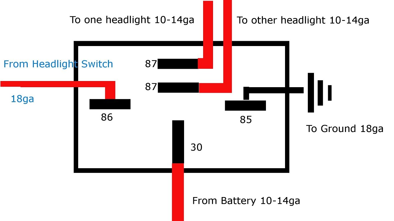
Why and How to Relay Headlights - YouTube
Any Electronics Engineers on here
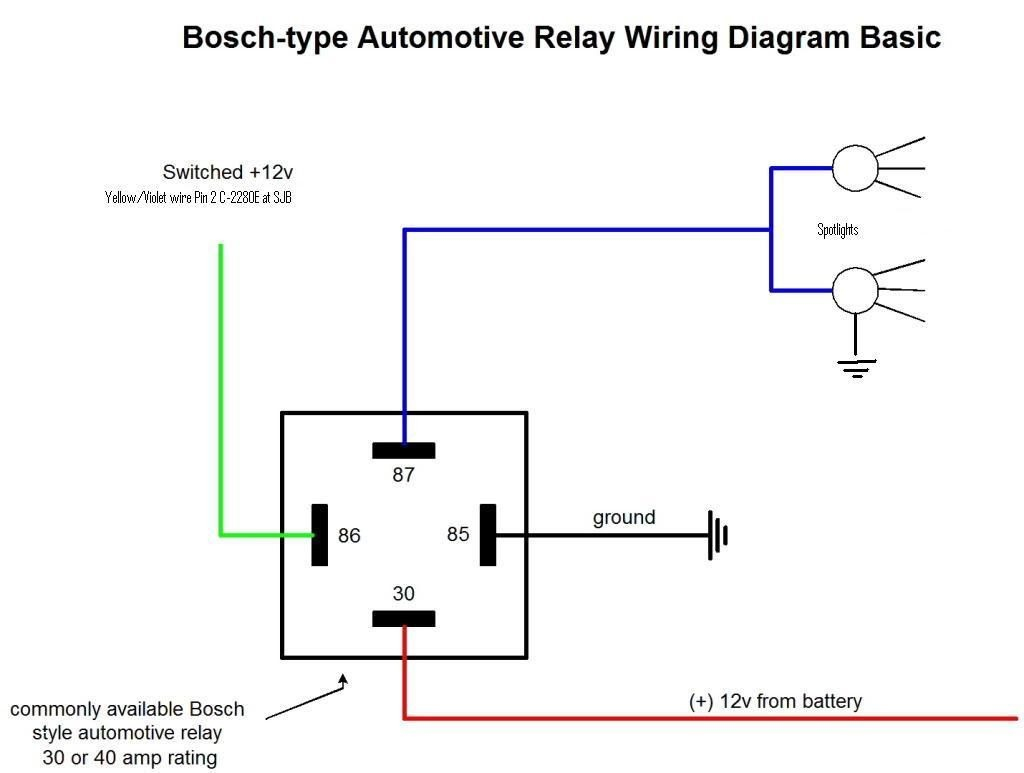
Automotive Relay Guide | 12 Volt Planet
Square D 100 Amp Panel Wiring Diagram Collection | Wiring ...
EP27 FLASHER 5 PIN

12v 5 Pin Relay Wiring Diagram Driving Lights How To Wire ...

12v Automotive Relay — 5 Pin 40AMP | MGI SpeedWare

Great Wiring Diagram For Horn Relay HORN RELAY Simple ...
Identify the hot power wire (red wire in the diagram above) in the cord leading to the light bulb and make a cut. The input pins of the module work inversely. We just need: Connect an Arduino's pin to the IN pin of the relay.
