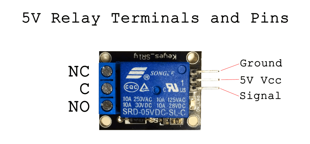
5 Pin Relay Connection Diagram. On the switched circuit side of the module, you'll see the three switched connection points marked with the diagram shown below (the labels NO, Common, and NC. The output voltage on this pin is what triggers the relay.
An AC bulb is used for demonstration.
On the switched circuit side of the module, you'll see the three switched connection points marked with the diagram shown below (the labels NO, Common, and NC.
Ac Relay Wiring Diagram - Relay Wiring Diagram | Wiring ...
How to Set Up a 5V Relay on the Arduino - Circuit Basics

12v Automotive Relay — 5 Pin 40AMP | MGI SpeedWare

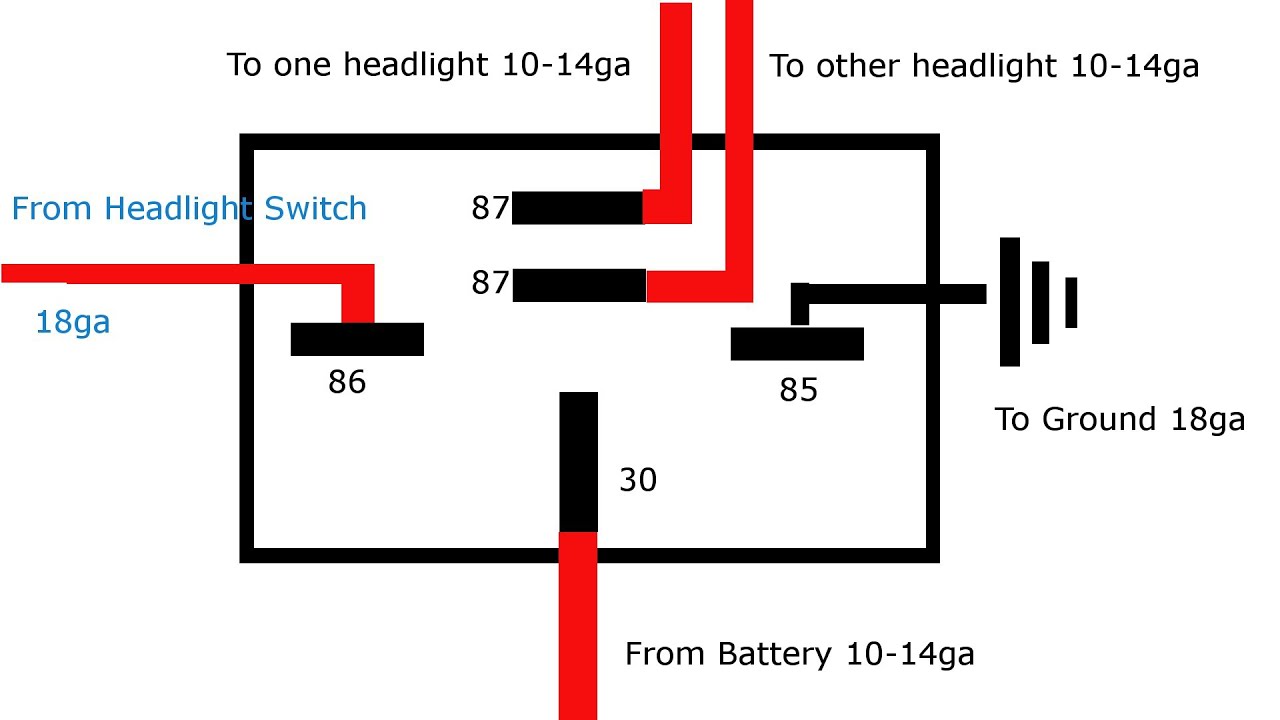
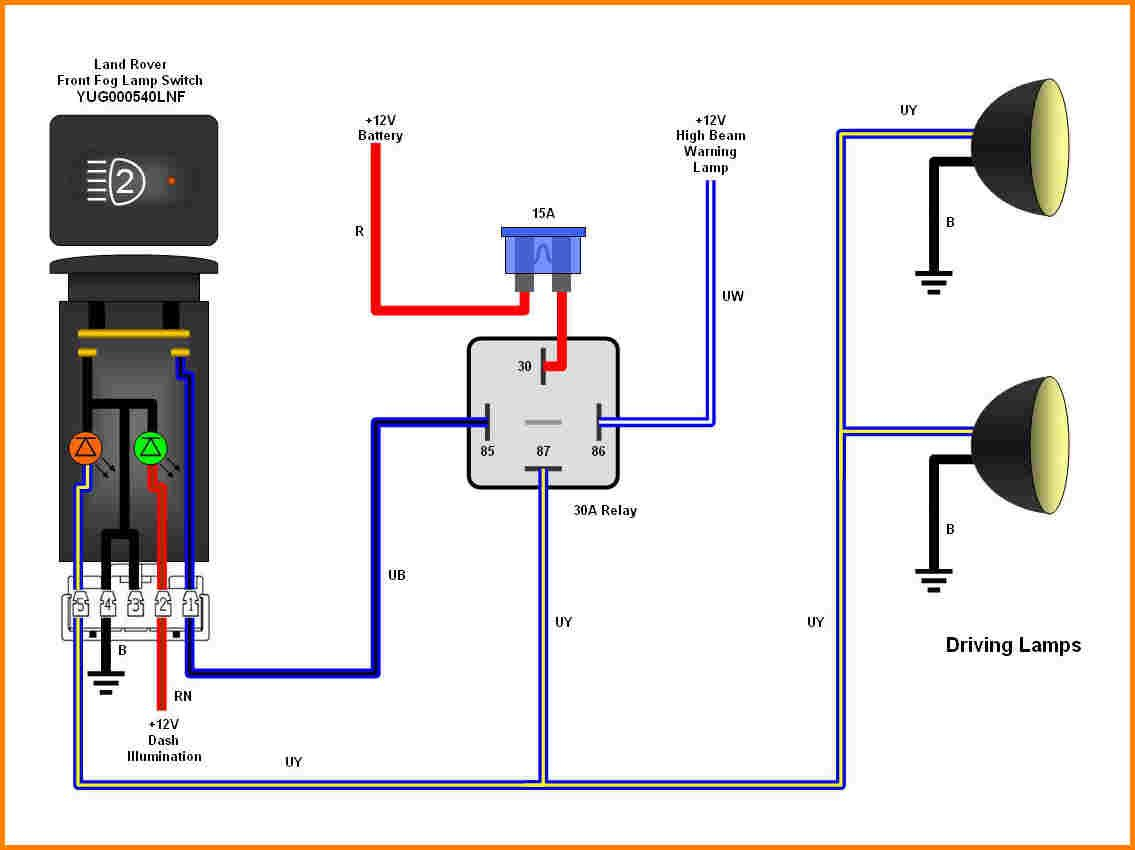
5 Pin Relay Wiring Diagram Driving Lights — UNTPIKAPPS

Automotive Relay Guide | 12 Volt Planet | Car audio ...

Relay – Mohan's electronics blog

(5 pack) Nilight Automotive Relay Harness Set 5-Pin 30/40A ...

Pico Mini Relay with 5 Pin Connector - Auto Wiring ...

12V Relay Wiring Diagram 5 Pin - fitfathers.me
If connected to NO the load remains disconnected before trigger. Use an ohmmeter to find the pins with continuity, and some resistance that will indicate that you have found the coil that is the electromagnet to activate the relay. once you have found those two pins Google the part number plus the word "datasheet". This single relay module can be used in interactive projects.
