4 G Signal Booster Circuit Diagram Pdf. The guard signal is active HIGH: • At thermal overshoot • During The internal guard circuit will not be activated, if the input signals on pins INP and INN delivered from the driver circuit. booster gsm antenna datasheet, cross reference, circuit and application notes in pdf format. This is the most critical step of the installation process because it will determine the overall performance of the booster system.

The guard signal is active HIGH: • At thermal overshoot • During The internal guard circuit will not be activated, if the input signals on pins INP and INN delivered from the driver circuit. booster gsm antenna datasheet, cross reference, circuit and application notes in pdf format.
This is the most critical step of the installation process because it will determine the overall performance of the booster system.

Onida Tv Circuit Diagram Pdf - passionpiratebay

HomeMade DIY HowTo Make: 4G Signal booster / amplifier ...

Mobile Network Booster Circuit Diagram | Circuit diagram ...
Homemade Cell Phone Signal Booster Circuit Diagram ...

Verizon 4G LTE Wireless Signal Booster
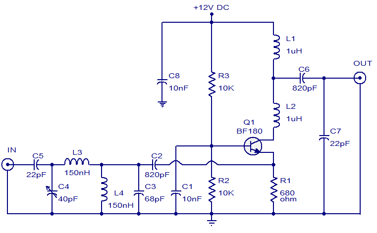
PG1N's HAM Radio Site - Transistors BF-Serie - BF180

Make Your Own Cell Phone Signal Booster for 2G-3G-4G ...

How to light up 24 LEDs using 1 x AA battery 1.42 volt ...

Cell Phone 4G LTE Repeater / Booster / Femtocell | Hackaday.io
The internal guard circuit provides a blanking signal for the CRT. Subwoofer booster circuit is used to enhancing or boosting or increase the subwoofer amplifier, but it also can improve the quality of the bass sound on an amplifier or High Power Amplifier. The block diagram of the booster.
